Applicable Components: 0201~5050
Board size:50×50-650×370mm
Feeder inputs:max.112
placement capacity:47,000 CPH
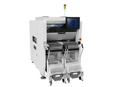
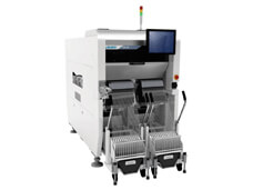
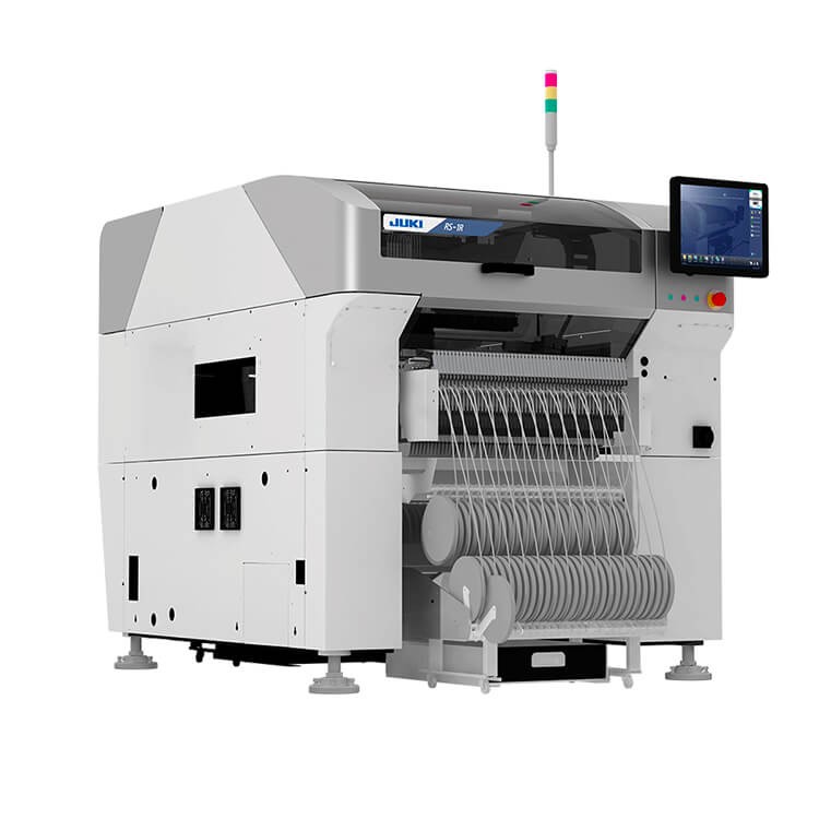
Product description: JUKI RS-1R Pick and Place Machine modular chip mounter Applicable Components: 0201~5050,Board size:50×50-650×370mm,Feeder inputs:max.112, placement capacity:47,000 CPH
JUKI RS-1R Chip mounter


Class leading speed, up to 47,000 cph
Newly developed “Takumi Head” with changing recognition sensor height
Optimum line balance and highest throughput
Wide component range from 0201 (metric) to large connectors and ICs
Optimal for LED placement
Electric Feeder Series
Supports stable supply of super small components.
High-Speed Compact Modular Mounter RS-1

The electric double tape feeder holds two 8mm reels in the space(17mm) of a single traditional tape feeder. This doubles the feeder capacity of the machine which means there is a greater chance of clustering boards into a single feeder setup. It also could reduce the total number of machines needed in a production line.

Electric Double Tape Feeder EF08HDR
The motor drive enables smoother component feeding and high-speed stable component supply. Lineup of feeders supporting 8-mm to 88-mm tapes: a variety of components from a subminiature component to a large one can be supported. Contribution to increased production efficiency with seeking improvement of the operability including a component pick-up position automatic correction function.

EF08HSR
Electric Tape Feeders and mechanical feeders can be switched by the batch exchange trolley
When batch exchange trollies are set to four feeder banks, the mounter automatically recognizes whether electrical feeders or mechanical feeders are set.
Effective utilization of assets
Existing mechanical feeders and batch exchange trollies can be used without any change.
Excellent setup workability
The feed pitch can be switched with one touch to improve the efficiency of the setup change operation.

Visualization of operational status
You can recognize the operating feeder and the feeder position at a glance thanks to LED indicators. If an error occurs, the corresponding LED indicator flashes to show you which feeder should be checked.

Component pick-up position correcting function
After a component is recognized, the position error information of a nozzle is reflecetd to a feeder. This feature allows you to automatically control the feeder so that components can be picked up at the same time stably.

Operability
Work to switch tape feeding pitch has been simplified. Status indication by LED increases efficiency of setup.
Function to adjust feeder pick up position
Pickup misalignment as a result of part centering is sent to the feeder for automatic control of simultaneous pickup at stable pickup positions.

Stable supply
By suppressing vibration, parts positions can be stabilized, realizing smooth and rapid supply of super small components.

High-speed, on-the-fly centering
on-the-fly centering
A high resolution laser is mounted on the head to center components in all directions including angle. Centering is done on-the-fly, allowing high speed placement of components from small chips to SOPs.
Adaptable centering

on-the-fly centering
Centering accommodates component variations
Laser centering measures the components on the side. It is not affected by variations of component color or width/length so, unlike vision centering, there is no need to edit component data for different component vendors.
Component check function improves placement reliability
Since the laser is mounted on the head, it can be used to monitor the presence of components the entire time from pick to placement. This is difficult to accomplish with vacuum detection only. The placement reliability is also improved because the release of the component is confirmed after placement.

Vision centering technology
method can be selected based on component type, shape, size and material. Laser centering is used for high speed placement of smaller components. Vision is used when lead or ball inspection is needed or when the component is too large for the laser. Many nozzles are available for odd-shaped components providing unsurpassed component handling.

General Vision
General vision function is used to support a wide variety of today’s unusual vision centered components. After programming is complete, the data can be verified by picking and test centering a component.

Line management function
Production program download / upload / monitoring
Software to download, upload, and monitor production programs sent to the line.
Each line*1 controlled separately. Production status monitor for individual lines.

Multi-line management
Production program download / upload / monitoring can be performed on multiple lines*2.
*2 Maximum 15 machines total for all lines
ISM (storage tower) interface

Data creation function
Cluster optimization
Cluster optimization groups several different production files together in a common feeder setup. It reduces changeover time by eliminating the need to setup feeders between jobs.

Flexline Cad*
Data conversion system to convert text data files generated by CAD systems or output from other machines to JUKI data format. Users can choose from pre-defined input formats or define and save custom conversion formats.
Extension function
Line Manager
A client PC delivers production programs to each machine in the line and manages the entire line. Production and machine management data is collected and consolidated. With the optional external output function, you can interface with MES software
Data Manager(Please contact us for availability.)

JaNets Basic Software

Fast Smart Modular Mounter | |||||
Model | RS-1R | ||||
Conveyor specification | standard | 150mm conveyor extensions, | 250mm conveyor extensions, | ||
Board size | minimum | 50×50㎜ | |||
maximum | 1 buffer | 650×370 ㎜ (Single clamping) | |||
950×370 ㎜ (double clamping) | 1,100×370 ㎜ (double clamping) | 1,200×370 ㎜ (double clamping) | |||
3 buffers | 360×370㎜ | 500×370㎜ | 600×370㎜ | ||
Component height | 25㎜ | ||||
Component size | 0201*1 ~74 ㎜ /150×50 ㎜ | ||||
Placement speed | Optimum | 47,000CPH | |||
IPC9850 | 31,000CPH | ||||
Placement accuracy | ±35μm(Cpk≧1) | ||||
Feeder inputs | max.112*2 | ||||
*1 For metric 0201 compliance please contact us.
*2 Using RF(RF08AS) feeders

Keywords:
SMT pick and place machine, Hanwha HM520 Plus Pick and Place Machine, Hanwha DECAN S2 Pick and Place Machine, JUKI RS-1R Chip Mounter, JUKI RX-8 pick and place machine, Yamaha Z-TA-R YSM40R Pick and Place Machine, Hanwha Chip Mounter, JUKI Pick and Place Machine, Yamaha Pick and Place Machine, Panasonic Pick and Place Machine, FUJI Pick and Place Machine, Siemens Pick and Place Machine.
Efficient Technology Co., Ltd provide a full SMT assembly line solutions, including SMT Assembly Line, Pick and place machine, Insert Plug-in machine, SMT Reflow oven, Wave Soldering Machine, SMT Stencil Printer, SMT Inspection machine, SMT Peripheral Equipment, SMT Spare Parts etc any kind SMT machines you may need, please Contact us for more information: Wechat : +86 13714564591, Skype : sales@effsmt.com, Email : sales@effsmt.com

Contact: Jacky
Phone:
E-mail: sales@effsmt.com
Add: No. 4, Yangyong Industrial Zone, Shapu Community, Songgang Street, Baoan District, Shenzhen